| Article number | Page number | Drawing number | Model Name | Specification
size mm | Remarks |
| JB-1 | 3 | 0-2a | Rotating payment(lower pair) | 180×100×160 | Bearing type |
| 2 | 3 | 2b | Mobile payment(lower pair) | 180×80×80 |
|
| 3 | 3 | 2c | Spiral pair(lower pair) | 150×80 |
|
| 4 | 3 | 3a | Rolling wheel contact(higher pair) | 200×120×160 |
|
| 5 | 3 | 3b | Cam contact(higher pair) | 200×120×280 |
|
| 6 | 3 | 3c | Gear contact(higher pair) | 200×120×280 |
|
| 7 | 6 | 1-1Q | External cylindrical friction wheel drive |
|
|
| 8 | 6 | 1b | Internal cylindrical friction wheel drive |
|
|
| 9 | 6 | 2Q | External conical friction wheel drive |
|
|
| 10 | 6 | 2b | Internal cone friction wheel drive |
|
|
| 11 | 7 | 3 | Friction press |
|
|
| 12 | 8 | 4Q | Parallel belt drive |
|
|
| 13 | 8 | 4b | V-belt drive | 240×120×200 |
|
| 14 | 8 | 4c | Circular belt drive |
|
|
| 15 | 8 | 4Q | Synchronous toothed belt drive | 240×120×220 |
|
| 16 | 17 | 10Q | Horizontal transmission(V-belt) | 240×120×220 |
|
| 17 | 17 | 10b | Vertical transmission(V-belt) |
|
|
| 18 | 17 | 1-10c | Gravity automatic tensioning(V-belt) |
|
|
| 19 | 18 | 11Q | Parallel belt tensioning wheel |
|
|
| 20 | 18 | 11b | Triangle belt tensioning wheel | 240×120×220 |
|
| 21 | 19 | 2-1Q | Single thread right-hand thread | 60×150 |
|
| 22 | 19 | 1b | Double thread left-hand thread | 60×150 |
|
| 23 | 19 | 1c | Three thread right-hand thread | 60×150 |
|
| 24 | 20 | 表2-1 | 6 commonly used thread profiles | 60×150 |
|
| 25 | 25 | 2-7 | Desktop vice with screw displacement | 200×140×120 |
|
| 26 | 25 | 2-8 | Screw jack | 200×120×200 |
|
| 27 | 26 | 2-9 | Screw in situ rotation and nut reciprocating motion | 200×120×200 |
|
| 28 | 26 | 2-10 | Nut in situ rotating screw reciprocating motion | 200×120×120 |
|
| 29 | 26 | 2-11 | Differential screw mechanism |
|
|
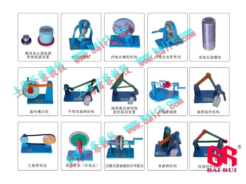
| 30 | 27 | 2-12 | Fine adjustment boring tool for differential spiral transmission |
|
|
| 31 | 27 | 2-13 | Ball screw drive | 立體蓋有機(jī)玻璃 |
|
| 32 | 29 | 3-1 | Chain drive | 240×120×200 |
|
| 33 | 32 | 3-7 | Spur gear transmission | 240×120×200 |
|
| 34 | 32 |
| Internal gear meshing transmission |
|
|
| 35 | 32 |
| Gear mesh transmission | 200×120×160 |
|
| 36 | 32 |
| Helical gear transmission | 200×120×200 |
|
| 37 | 32 |
| herringbone gear | 200×120×200 |
|
| 38 | 32 |
| straight bevel gear | 200×150×150 |
|
| 39 | 32 |
| Bevel helical gear transmission |
|
|
| 40 | 32 |
| Conical curved tooth gear transmission |
|
|
| 41 | 32 |
| worm drive | 200×120×280 |
|
| 42 | 32 | 1-7 | Spiral gear transmission |
|
|
| 43 | 32 | 1-7 | Hyperbolic bevel gear transmission |
|
|
| 44 | 33 | 3-8 | Involute formation | 220×80×300 |
|
| 45 | 33 | 9 | Formation of involute contours |
|
|
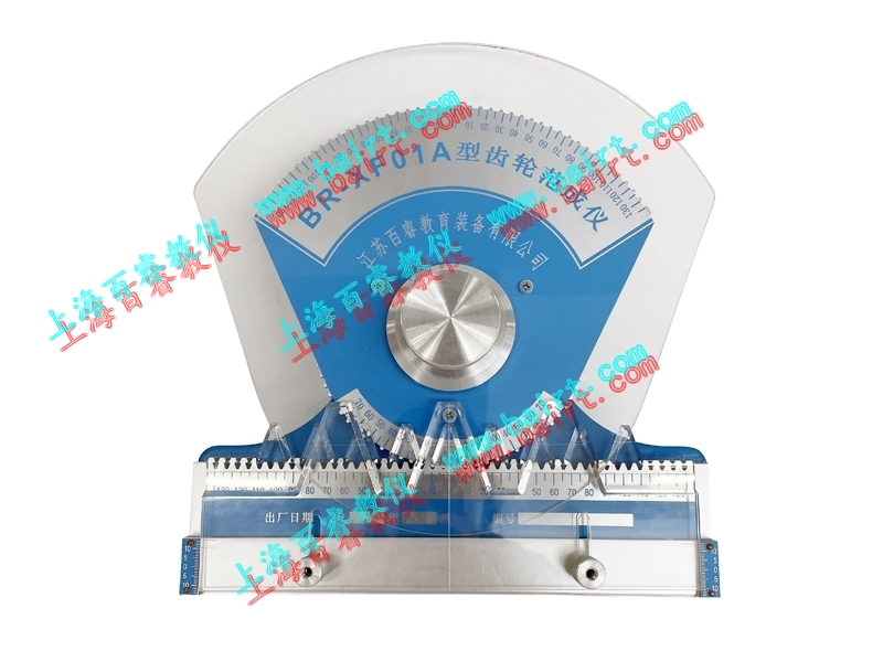
| 46 | 43 | 22 | Correct meshing conditions for involute gears | 400×500 Teaching board |
|
| 47 | 46 | 29 | Cone friction wheel |
|
|
| 48 | 48 | 31Q | Method for machining disc milling cutters using profiling |
|
|
| 49 | 49 | 31b | Method for machining finger shaped milling cutters using profiling |
|
|
| 50 | 49 | 32 | Principle of gear machining using a gear cutter |
|
|
| 51 | 49 | 33 | Gear undercutting phenomenon | Independent root cutting |
|
| 52 | 50 | 34 | Analysis of Root Cutting Formation Process |
|
|
| 53 | 60 | 53 | Manual hoist schematic diagram | 200×120×400 |
|
| 54 | 64 | 4-1Q | Fixed axle gear system | 250×200×200 |
|
| 55 | 64 | 1b | Revolving Wheel (External Gear) | 200×120×280 |
|
| 56 | 65 | 4-2 | A pair of internal meshing gears |
|
|
| 57 | 66 | 4 | Bevel gear wheel display |
|
|
| 58 | 66 | 5 | Calculation model for transmission ratio of fixed axis gear trains | 250×250×280 |
|
| 59 | 68 | 6 | Fixed shaft wheel indication for worm gear transmission |
|
|
| 60 | 68 | 7 | Variable speed mechanism composed of sliding gears |
|
|
| 61 | 69 | 8 | Grinding machine grinding wheel holder feed mechanism |
|
|
| 62 | 70 | 10 | Schematic diagram of the winding machine transmission system |
|
|
| 63 | 70 | 11 | Gear hobbing machine worktable transmission system |
|
|
| 64 | 73 | 5-1 | revolute four-bar mechanism | 240×120×250 |
|
| 65 | 74 | 2 | Crank connecting rod mechanism | 240×120×250 |
|
| 66 | 74 | 3 | Cross feed mechanism of cattle head planer | 240×120×200 |
|
| 67 | 75 | 4Q | Example of a scissor machine with a crank connecting rod mechanism |
|
|
| 68 | 75 | 4b | Example crusher with crank connecting rod mechanism |
|
|
| 69 | 75 | 4c | Example of a crank connecting rod mechanism mixer |
|
|
| 70 | 75 | 4d | The shaking device for the pitch angle of the crank radar |
|
|
| 71 | 75 | 5-5 | Sewing machine pedal mechanism |
|
|
| 72 | 75 | 6 | Double crank mechanism | 200×120×200 |
|
| 73 | 76 | 7 | Inertial sieve |
|
|
| 74 | 76 | 8Q | Parallel double crank mechanism |
|
|
| 75 | 76 | 8b | Reverse double crank mechanism |
|
|
| 76 | 77 | 6 | Locomotive active wheel linkage device |
|
|
| 77 | 77 | 10 | Two sets of wheel misalignment devices |
|
|
| 78 | 77 | 11 | Door opening and closing mechanism |
|
|
| 79 | 77 | 12Q | Automatic tipping device |
|
|
| 80 | 77 | 12b | Port crane |
|
|
| 81 | 78 | 13Q | Plane Undercarriage Mechanism |
|
|
| 82 | 78 | 13b | Vehicle front wheel steering mechanism |
|
|
| 83 | 80 | 15 | Dead center mechanism |
|
|
| 84 | 81 | 16Q | Crank slider mechanism | 240×120×150 |
|
| 85 | 81 | 16b | Eccentric wheel mechanism | 240×120×200 |
|
| 86 | 82 | 17Q | Crank slider mechanism (pressure mechanism) | 240×120×200 |
|
| 87 | 82 | 17b | Single cylinder internal combustion engine | 240×140×300 |
|
| 88 | 82 | 17c | Twisting mechanism |
|
|
| 89 | 82 | 17d | Automatic feeding device |
|
|
| 90 | 82 | 18Q | Guide rod mechanism (crank slider mechanism) | 200×120×250 |
|
| 91 | 82 | 18b | Guide rod mechanism |
|
|
| 92 | 82 | 18c | Guide rod mechanism (swinging slider mechanism) |
|
|
| 93 | 82 | 18d | Guide rod mechanism (fixed slider mechanism) |
|
|
| 94 | 83 | 5-19Q | The swinging guide rod mechanism for the application of cattle head planer | 240×150×300 |
|
| 95 | 83 | 19c | Fixed slider mechanism for pump applications |
|
|
| 96 | 86 | 6-1Q | Internal combustion engine air tightness mechanism | 200×120×300 |
|
| 97 | 86 | 1c | The tool feeding mechanism of an automatic lathe |
|
|
| 98 | 87 | 2 | Disc-shaped groove cam |
|
|
| 99 | 87 | 3 | Mobile cam mechanism |
|
|
| 100 | 87 | 4 | End face cylindrical cam mechanism | 240×120×200 |
|
| 101 | 88 | surface6-1 | Pointed cam mechanism | 200×140×300 |
|
| 102 | 88 | surface6-1 | Roller cam mechanism | 200×140×300 |
|
| 103 | 88 | surface6-1 | Flat bottomed cam mechanism | 200×140×300 |
|
| 104 | 88 | surface6-1 | Curved cam mechanism |
|
|
| 105 | 89 | 6-5 | Displacement curve of cam mechanism |
|
|
| 106 | 94 | 7-1 | Variable speed mechanism composed of sliding gears | 450×350×260 |
|
| 107 | 95 | 3 | Multiplying transmission mechanism |
|
|
| 108 | 96 | 4 | Pulling key variable speed mechanism |
|
|
| 109 | 97 | 6 | Conical wheel continuously variable transmission mechanism |
|
|
| 110 | 98 | 7 | Samsung gear directional mechanism |
|
|
| 111 | 98 | 8 | Sliding gear directional mechanism |
|
|
| 112 | 98 | 9 | Bevel gear directional mechanism |
|
|
| 113 | 99 | 10 | crank shaft ratchet | 240×120×220 |
|
| 114 | 99 | 11 | Adjusting the Ratchet Angle by Changing the Length of the crank |
|
|
| 115 | 100 | 12 | Adjusting the Ratchet Angle with a Masking Handle | 240×120×220 |
|
| 116 | 101 | 13Q | Double acting symmetrical pawl |
|
|
| 117 | 101 | 13b | Double acting ratchet mechanism |
|
|
| 118 | 101 | 13c | Friction type ratchet mechanism |
|
|
| 119 | 101 | 13d | Ratchet mechanism to prevent reversal |
|
|
| 120 | 102 | 15 | Single cone external meshing groove wheel mechanism | 240×120×220 |
|
| 121 | 104 | 18Q | Internal meshing groove wheel mechanism |
|
|
| 122 | 104 | 18b | Double circular pin external meshing groove wheel mechanism | 240×120×220 |
|
| 123 | 104 | 19Q | Single tooth intermittent gear mechanism |
|
|
| 124 | 104 | 19b | Multi tooth intermittent gear mechanism |
|
|
| 125 | 105 | 20 | Intermittent mechanism for suppressing and monitoring coal workbenches |
|
|
| 126 | 105 | 21Q | Single rack intermittent mechanism |
|
|
| 127 | 105 | 21b | Double rack intermittent mechanism |
|
|
| 128 | 105 | 22 | Space intermittent mechanism |
|
|
| 129 | 107 | 8-1Q | Ordinary wedge key connection |
|
|
| 130 | 107 | 1b | A pair of tangential key connections |
|
|
| 131 | 108 | 2Q | Ordinary flat key structure |
|
|
| 132 | 108 | 2b | Ordinary flat key form A type B type C type |
|
|
| 133 | 108 | 3 | Guiding flat key connection | 180×130 |
|
| 134 | 108 | 4 | Half circular key connection | 180×130 |
|
| 135 | 109 | 5 | Three types of spline connections (Q.b.C) | 180×90 |
|
| 136 | 113 | 7 | Example of selecting flat keys |
|
|
| 137 | 113 | 8 | Pin for positioning |
|
|
| 138 | 114 | 10Qb | Pins for transmitting force or torque (two types) |
|
|
| 139 | 114 | 11Q | Type of shaft, crankshaft |
|
|
| 140 | 114 | 11b | optical axis |
|
|
| 141 | 114 | 8-11c | Stepped axis |
|
|
| 142 | 115 | 12Q | Rotating spindle |
|
|
| 143 | 115 | 12b | Fixed spindle |
|
|
| 144 | 116 | 15 | Common axis structures |
|
|
| 145 | 117 | 17Q | With locking device |
|
|
| 146 | 117 | 17b | Cone end positioning |
|
|
| 147 | 118 | 18 | Double nut fixation |
|
|
| 148 | 118 | 18b | Nut with retaining washer |
|
|
| 149 | 118 | 19Q | Cone pin fixation |
|
|
| 150 | 118 | 19d | Elastic retaining ring fixation |
|
|
| 151 | 118 | 19c | Fixed with fastening screws |
|
|
| 152 | 121 | 23 | Split sliding bearings |
|
|
| 153 | 130 | 34Q | Collar type coupling groove fit | 200×120×200 |
|
| 154 | 130 | 34b | Collar coupling split ring fit | 200×120×200 |
|
| 155 | 132 | 36 | Gear coupling | 200×120×200 |
|
| 156 | 132 | 37 | Cross slider coupling | 200×120×200 |
|
| 157 | 132 | 38 | Elastic ring cylindrical pin coupling | 200×120×200 |
|
| 158 | 132 | 39 | Nylon bolt coupling | 200×120×200 |
|
| 159 | 133 | 40Q | Shear pin safety coupling flange plate shear pin | 200×120×200 |
|
| 160 | 133 | 40b | Shear pin safety coupling sleeve simple shear pin | 200×120×200 |
|
| 161 | 133 | 41 | Universal coupling | 200×120×200 |
|
| 162 | 134 | 42 | Side gear clutch | 200×120×200 |
|
| 163 | 134 | 43 | Circular disc friction gear closer | 200×120×200 |
|
| 164 | 135 | 44 | Multi plate friction clutch | 200×120×200 |
|
| 165 | 135 | 46 | One-way clutch |
|
|
| 166 | 136 | 47 | Conical brake |
|
|
| 167 | 136 | 48 | Band brake |
|
|





 Return to homepage
 Immediately call for consultation
 About Us
 Immediately consult online